|
Heating
| NOTE: Since getting the HV-Pro
I use the onboard relays instead of two relays in a project box. The
operation is still the same, just without external relays. |
This is really simple, and it works beautifully. Inside the box are two
relays. One is normally open and one is normally closed [they're actually
two identical relays, but I use the N.O. contacts on one and the N.C.
contacts on the other] and they're connected to the thermostat on the
first floor. The thermostat is a basic mechanical model and has one pair
of wires going to the boiler. When the wires are shorted the boiler comes
on.
The N.O. relay connects across these wires and when HV energizes it the
boiler comes on regardless of the status of the thermostat. The N.C. relay
has been placed in-line with one of the wires. When it opens, and breaks
any potential circuit, the thermostat can no longer call for heat. So HV
has two possible operations: Interrupt Heat, and Demand Heat.
Even though we have a two family house there is only one boiler and
there are no zones. To compound this problem the thermostat is on the
first floor which tends to warm up before the second floor. My solution
was to run a piece of CAT5 to the second floor and stick
a project box on the end. This box has a DS18S20 temperature sensor in it. So
I can have a minimum temperature set for that floor and HV can override
the thermostat if it needs to.
HV also interrupts the heat when it isn't needed. In our case,
"isn't needed" is defined as either: "nobody is home,"
or "everyone is asleep." Because we arm our alarms in stay mode
when we go to bed all HV needs to do is monitor the status of the alarm to
determine when to cut out the heat. If both partitions are armed [in
either away or stay mode] HV opens the N.C. relay. And in the morning, a
half hour before we wake up [6:00am on weekdays] HV closes the N.O. relay
and the house is nice a toasty for us when we step out of the showers.
|

The box housing the relays and LEDs.
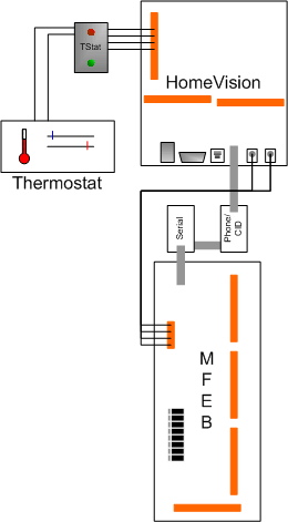
HV thermostat control schematic.
|
|
Cooling Cooling the house is handled by a single 15,100 BTU/hr wall
mounted A/C. Each floor is only 720 sq. ft. so this is more than adequate
for the first floor, and even spills into the ground floor to make it bearable.
One of the keys features that led me to choose this unit is that it comes
with an IR remote. So I taught HV the IR signals and it can now control the
A/C. But the problem is knowing the status. Is the A/C on or off? Because
the remote control uses a toggle for on/off, HV needs to know the status
before it decides whether or not to send the IR command. At first I tried
using a home built air flow sensor. I tried two designs that consisted of a
flap that would close a circuit when its position changed because of the
moving air. These would work for a couple of days, then something would
come out of alignment and they wouldn't close the circuit anymore. I
probably could have come up with a better design if I had used a mercury
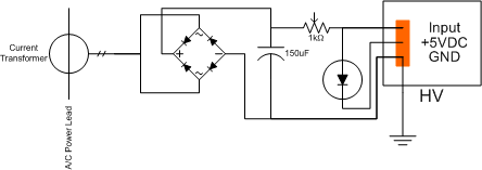
switch, but I decided to go another route. I bought a split-core
current transformer with the idea that I'd measure the current being drawn
by the A/C. Now I would be able to tell the on/off state of the A/C and
the on/off state of the compressor [and maybe, if the resolution was fine
enough, the hi/med/lo state of the fan]. So the transformer is placed
around one of the conductors of the A/C's power cord, and it's output goes
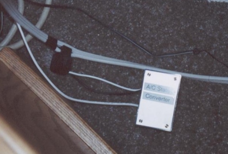
to a project box which contains a simple circuit to convert the 0-12VAC
output to 0-4VDC for one of HV's analog input ports.
|
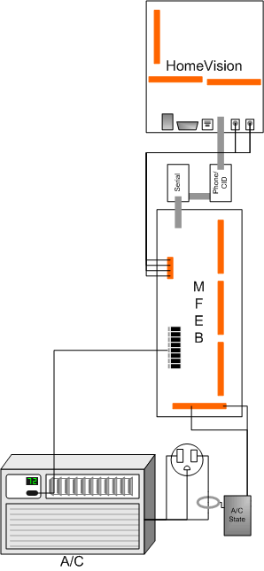
HV A/C control and feedback.
|